Check saturation first, temperature second
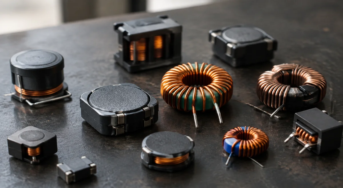
A power inductor has two current limits that answer two different questions. Saturation current (Isat) asks: at what current does the core stop behaving like an inductor? Temperature-rise current (Irms) asks: at what current does the part get too hot for its own good? Check Isat first, because its failure mode is sudden and violent — once the core saturates, inductance collapses, ripple current explodes, and the switching FETs absorb the punishment. A typical saturation trap: a board that survives bench tests but drops its output rail inside a hot enclosure, where the saturated inductor can no longer hold the switching ripple. Thermal failure, by contrast, is slow and gives you warning signs you can measure. The trap is that Isat numbers are not defined the same way everywhere. TDK rates its VLS series at a 30% inductance drop, while other makers use 10% or 20% — the same physical part earns a higher headline Isat at a looser threshold. Allied Components documents that its own storefront "current rating" field maps to Isat for some families and to Irms for others, so the datasheet table, not the search-result label, is the controlling source. Before comparing two parts, write down each maker's drop threshold next to the number; comparing a 10%-drop Isat against a 30%-drop Isat is comparing two different tests. In practice, compare worst-case instantaneous peak current — including what the converter does during startup, load steps and fault events — against Isat, and compare the calculated RMS current against Irms after derating for your enclosure. If you only have time for one derating exercise, spend it on Isat: thermal problems announce themselves in testing, saturation problems announce themselves in the field.
- Isat guards against magnetic collapse; Irms guards against overheating — check Isat first because its failure is immediate.
- Record the inductance-drop threshold (10%, 20% or 30%) beside every Isat number; never compare headline figures across makers without it.
- A generic "current rating" on a distributor page may mean Isat or Irms depending on the family — open the datasheet.
- Test your margin against peak current under transient and fault conditions, not steady-state nominal current.
Treat Irms as a thermal budget, not a spending limit
Irms is usually defined as the DC current that raises the part's temperature by a stated amount — commonly 40 °C — on the maker's test board, in still air, at room temperature. Your board is not that test board. Inside a sealed enclosure, next to hot FETs, with no airflow, the same current produces a larger rise, and the core materials and winding insulation age faster at every degree above their comfort zone. The correct move is to translate Irms into your thermal reality: start from the datasheet basis, subtract your worst-case ambient, and leave margin for the rest of the system heating the part from the outside. A common buyer mistake is sizing Irms against the converter's output current as if it were a hard ceiling, or worse, picking the part whose Irms is merely above the load and calling the job done. Irms should be compared against the true RMS inductor current — which in a buck converter exceeds the DC output current because of the ripple component — after thermal derating. When the enclosure runs hot or airflow is blocked, stepping up one size in Irms is usually cheaper than a field failure, and it costs far less than the efficiency you might gain by chasing the lowest DCR. Note how TDK lists the VLS6045EX-100M temperature-rise current as a typical value at 40 °C rise, while the saturation figure is a maximum at 30% inductance drop: two numbers, two statistical bases, two failure modes. If your procurement comparison treats them as interchangeable, it will eventually pick the wrong part.
- Irms is measured on the maker's test board in still air — derate for your ambient, enclosure and neighboring heat sources.
- Compare Irms against RMS inductor current (DC plus ripple), not against the converter's output current rating.
- In hot or sealed designs, buy Irms margin; it is the cheapest insurance on the bill of materials.
- Watch whether the datasheet value is typical or maximum before using it as a procurement limit.
DCR: lower is better, but it is never free
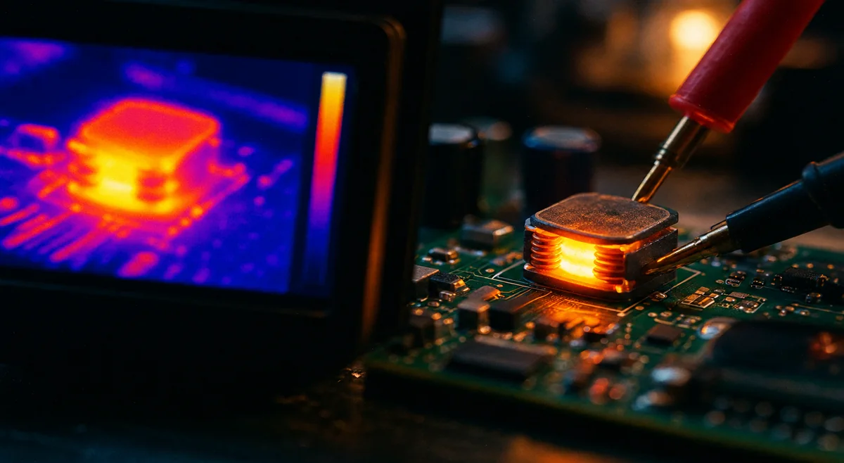
DC resistance turns load current into heat through simple I²R loss, so a lower DCR directly improves efficiency at heavy load. The catch is that DCR is bought with copper and size: for a given inductance, lower DCR generally means thicker wire, a bigger core, or a different construction — all of which cost board space and money. Shrinking DCR past the point of diminishing returns is how buyers end up with an oversized inductor whose saturation margin got traded away silently, because the larger winding sometimes comes with a smaller core cross-section in the same footprint family. There is also a frequency dimension that DCR-only comparisons miss. At high switching frequencies, AC winding losses from skin and proximity effects, plus core loss driven by ripple current, can outweigh the DC copper loss entirely. A part that wins the DCR contest at DC can lose the efficiency contest at 1 MHz. This is why the decision rule is: minimize DCR after Isat and thermal requirements are satisfied, not before. DCR is an optimization variable inside a feasible set, not the selection criterion. One practical habit: design against the maximum DCR, not the typical. The VLS6045EX-100M datasheet lists 47 mΩ typical and 61 mΩ maximum — a part bought at the typical value and validated at the maximum value behaves very differently in a worst-case efficiency calculation. Procurement specifications should quote the max, because the reel you receive is guaranteed to the max.
- Minimize DCR only after Isat margin and thermal requirements are locked in — never let a DCR comparison shrink the core.
- At high switching frequencies, AC winding loss and core loss can dominate; DCR alone misranks parts.
- Always design and specify against maximum DCR, not the typical value on the front page.
- A lower-DCR part in the same footprint may carry less saturation margin — check both numbers together.
Shielded vs unshielded is an EMI decision, not a quality grade
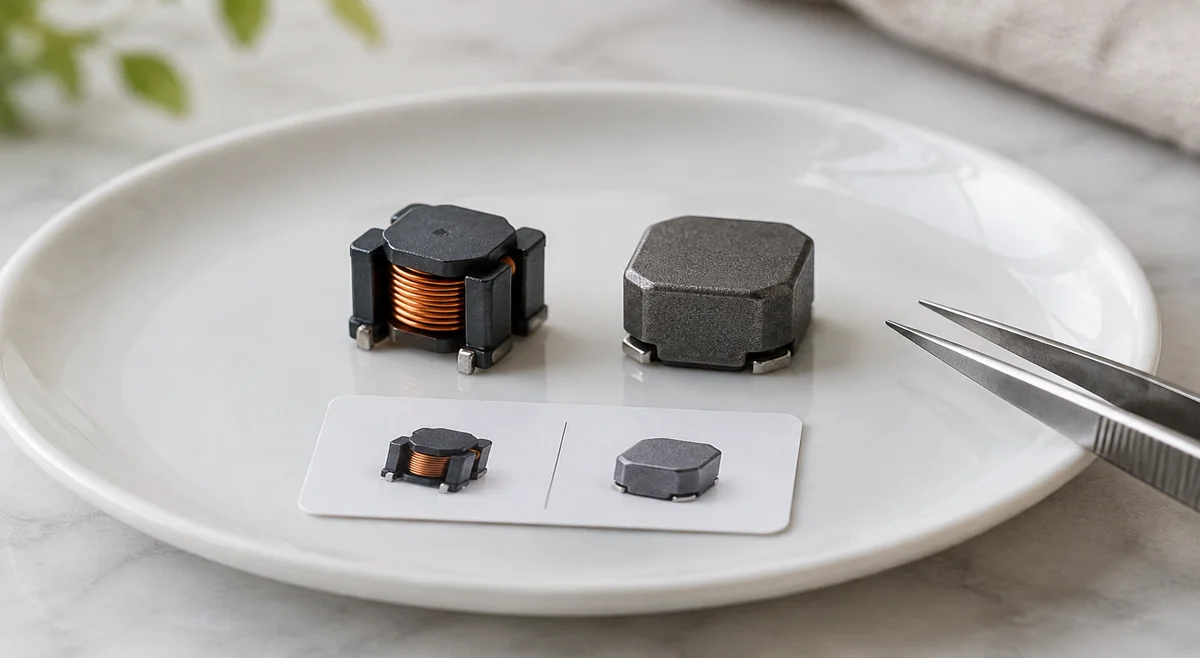
The current through a power inductor generates a magnetic field, and an unshielded construction lets more of that flux leak into the surrounding board area. Shielded construction wraps the winding in magnetic material to contain it. The selection question is therefore about the neighborhood, not the part: does anything sensitive sit nearby — ADC inputs, sensors, RF sections, high-speed interfaces, or another switching converter? If yes, shielded is the low-risk default; if the power stage sits in an electrically quiet corner with generous keep-out, unshielded can serve perfectly well at lower cost. The trade-off inside the shielded option is subtler than most guides admit. Würth Elektronik's design tips note that a shielded inductor of the same series achieves a higher AL value, which means lower DC resistance for the same inductance — but the larger core volume brings slightly higher core losses. So "shielded" is not strictly better electrically; it trades a little core loss for a lot of EMI containment. Layout discipline still applies either way: do not route traces under the part and do not stack boards directly above it, since coupling can occur through the remaining air gap even on shielded types. Semi-shielded constructions sit between the two, containing most of the flux at a middle cost point. The LQH32PN100MNCL, for example, uses a magnetic-resin shield around its winding in a compact 3225 footprint — a reasonable middle ground for dense boards where a fully molded part would be overkill but an open drum core would spray flux onto adjacent circuitry. Match the shielding level to the EMI risk, not to a vague sense of "better".
- Choose shielding by what sits next to the inductor (ADC, sensors, RF, other converters), not by part prestige.
- Shielded buys EMI containment at the price of slightly higher core loss — a trade, not a free upgrade.
- Keep-out discipline (no traces under, no boards above) applies to shielded parts too.
- Semi-shielded is the pragmatic middle for dense boards with moderate EMI sensitivity.
Core material in plain terms: ferrite vs metal powder
Roughly, power inductor cores fall into two camps. Ferrite cores hold their inductance flat and then saturate with a hard knee — the inductance falls off a cliff past a well-defined current. That predictability is why ferrite dominates high-frequency buck designs: the control loop model stays accurate right up to the knee, and core losses stay low at high switching frequencies. The price of that sharp knee is unforgiving behavior past it; exceed Isat on a ferrite part and the converter can go from stable to chaotic within one switching cycle. Metal-powder and other composite cores saturate softly: inductance rolls off gradually instead of collapsing, which makes them forgiving under current spikes, load dumps and other abuse. The trade is higher core loss and a knee that is harder to pin down on paper — the "Isat" of a soft-saturation part is a judgment call about how much roll-off your loop tolerates. Teams often discover that swapping in a composite-core part subtly reshapes the measured ripple waveform in ways the small-signal model never predicted, which is fine as long as the loop was validated with the real part, not the spreadsheet. The buying decision follows the application: pick ferrite when loop predictability and high-frequency efficiency matter most, which covers most buck converters above roughly 100 kHz; pick composite when the inductor must survive repeated transient abuse that would push a ferrite part over its knee. Either way, confirm the choice against the converter's current-limit behavior — startup into a discharged output capacitor and short-circuit recovery can drive peak currents far above the nominal operating point, and that is the peak your Isat margin must actually cover. The buck converter selection guide covers how converter-side choices set the current the inductor must survive. Send the shortlisted inductors on one RFQ with your Isat threshold, RMS current and worst-case ambient stated, so every quote is priced against the same derating assumptions.
- Ferrite: hard saturation knee, predictable loop behavior, low high-frequency core loss — but brutal past Isat.
- Metal powder / composite: soft saturation, forgiving under spikes, but higher core loss and a fuzzier knee.
- Size Isat against the converter's current-limit events (startup, short-circuit recovery), not nominal peak current.
- Validate the loop with the actual core material; soft-saturation roll-off changes the ripple the model predicts.
Frequently asked questions
Quick answers to the power-inductor questions buyers ask most.
- Q: Isat or Irms — which do I check first? A: Isat, against worst-case peak current including transients and fault events. Saturation fails suddenly; thermal problems give warning. Then check Irms against RMS current after derating for your enclosure.
- Q: Can I just pick the inductor with the lowest DCR? A: No. Minimize DCR only after Isat and thermal margins are satisfied — a DCR-only pick can silently trade away saturation margin, and at high switching frequencies AC and core losses can dominate anyway.
- Q: Do I really need a shielded inductor? A: If anything EMI-sensitive (ADC, sensors, RF, another converter) sits nearby, yes — shielding contains magnetic flux. For electrically quiet, spacious layouts, unshielded is fine with proper keep-out. Semi-shielded covers the middle ground.
- Q: Ferrite or metal-powder core for a buck converter? A: Ferrite for most buck designs — predictable saturation knee and low high-frequency core loss. Metal powder when the inductor must absorb repeated current spikes without a hard collapse, accepting higher core loss.
Sources
Use the latest guidance for the exact part and manufacturer when deciding acceptance criteria.
- TDK Product Center — VLS6045EX-100M detailed specifications
- Murata — LQH32PN100MNCL datasheet (via Octopart mirror; verify against murata.com for the latest revision)
- Würth Elektronik via element14 — 8 design tips for power inductor selection
- Allied Components — Power inductor design guide (Isat vs Irms definitions)