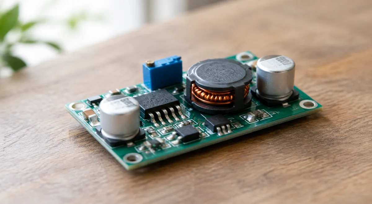
Two numbers lock the topology
Buck selection starts with two numbers: load current and the input-to-output ratio. Together they decide the topology before any part number enters the picture. A large step-down ratio at high current means the switch spends most of each cycle off while the freewheeling path conducts — conduction loss dominates, and the topology choice matters enormously. A small ratio at light current is a different design entirely, where switching loss and quiescent current outweigh raw conduction. Sketch these two numbers first: they tell you whether the choice is synchronous or asynchronous, which current class the design sits in, and roughly how hot it will run. Everything after this is refinement.
Synchronous or not: the efficiency decision
The synchronous-versus-asynchronous choice is the highest-leverage decision in buck selection. Replacing the freewheeling diode with a second MOSFET removes the diode forward-voltage loss — decisive at low output voltages and high currents, where a 0.5 V diode drop against a 3.3 V output is efficiency discarded every cycle. The price is complexity: a synchronous design needs proper dead-time control and usually costs more in silicon and design attention. For high-current or low-voltage outputs, synchronous wins clearly. For light loads, simple supplies, or the fastest route to market, the asynchronous classic remains rational — its simplicity is a feature, not a compromise. Let the output voltage and current from the first section make this call; do not let habit make it.
Switching frequency is a three-way trade
Switching frequency trades inductor size against efficiency against EMI — favor two, and the third bills you later. Higher frequency shrinks the inductor and the output capacitors, which is why compact modules run fast; but every switching edge burns energy and radiates noise, so efficiency and EMI both suffer. Lower frequency is kinder to efficiency and easier on EMI filtering, at the cost of bulkier magnetics. Near noise-sensitive RF or precision analog sections, the lower-frequency part with a shielded inductor is usually the calmer neighbor. There is no universally right frequency, only the right compromise for the board it lives on — decide it from the mechanical and noise constraints, not from the parametric table.
The inductor and layout decide the result
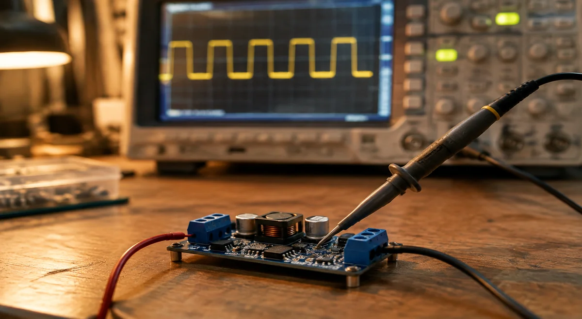
In buck design, the inductor and the PCB layout decide the outcome more than the controller chip. Size the inductor for saturation current with genuine margin above the peak switch current — an inductor that saturates under transient load turns a well-chosen converter into a failing one. Then lay out for minimum switch-loop area: tight input-capacitor placement, a short high-current loop, and the feedback node routed away from the switching node. Most buck chip problems debugged in the field are layout problems wearing a chip’s name. When the same converter gets swapped more than once, check the layout before blaming the batch: a long, looping input trace produces exactly the symptoms of a 'bad batch'. Layout first, part second. Review the layout checklist with the same seriousness as the part selection, following the layout guidance in the exact device’s datasheet rather than a generic app note.
Selection snapshot: three real parts
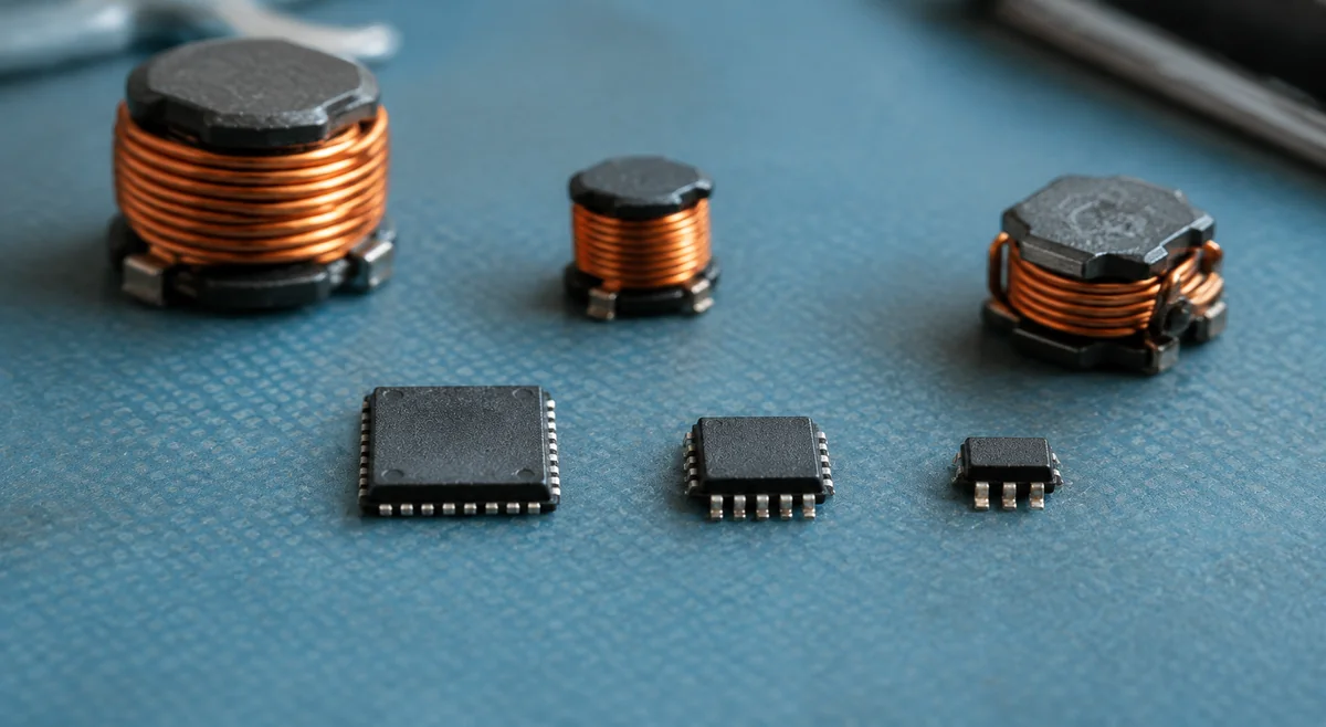
Three stocked parts map the decision space end to end. LM2596S-3.3/NOPB is the asynchronous classic: fixed 3.3 V, simple to apply, and forgiving — the right answer when reliability and design speed beat peak efficiency. TPS54360DDAR is the synchronous wide-input workhorse for higher-current designs or higher input voltages, where the diode loss of an asynchronous approach would hurt. MP9943GQ-Z is the synchronous high-frequency option in a small SOT583 package for space-constrained boards that can meet its stricter layout demands. The progression is not good, better, best — it is simple, wide-input, compact — and the current, ratio, and board constraints from the earlier sections point at exactly one of them.
Market reality and buying practice
The LM2596 family is one of the longest-lived and most widely listed buck series on HQBuy and LCSC — decades in production mean deep second-source coverage and broad module availability. That longevity demands suffix discipline: the 3.3 V, 5 V, and adjustable versions are different orderable devices, and quoting the family name alone is how the wrong reel gets ordered. This is one of the most common RFQ corrections: the buyer writes the family name, and the quotation comes back for a version the BOM never approved. One suffix, one line, on every RFQ. A Douyin video by @安信泰单片机 (24 likes, observed 2026-09-30) documents the same field symptom — a buck rail that collapses once loaded — BUCK电路为什么一带载电路就塌. For procurement, search the complete ordering code on the marketplace for real-time listings, confirm the voltage-version suffix character for character, and put the exact code — plus the inductor and capacitor requirements — into the RFQ.
- Never quote the family name alone — the voltage-version suffix selects a different device.
- Include the inductor and key capacitors in the sourcing check; a buck is a circuit, not a chip.
- Reconfirm availability for your quantity; broad listing coverage is a lead, not a guarantee.
Buck-then-LDO: the hybrid answer
When the design demands both efficiency and quiet rails, stop choosing between the buck and the LDO and stack them. The buck does the heavy lifting — dropping the large input-to-output gap at high efficiency — while a small LDO post-regulator cleans the rail for the noise-sensitive load. The LDO sees only a small voltage drop, so its dissipation stays modest, and its high power-supply rejection scrubs the switching ripple the buck leaves behind. This is the standard architecture behind RF front ends and precision analog supplies: buck for the volts, LDO for the silence. The cost is real — two stages, more board area, two sets of passives — so reserve it for loads that genuinely need it rather than defaulting to it everywhere. Size the buck for the bulk conversion using the framework above, then pick the LDO for dropout, noise, and quiescent current on the small remaining drop. When both stages are chosen for their actual jobs, the combination outperforms either device alone.
Frequently asked questions
Quick answers to the questions buyers ask most about choosing buck converters.
- Q: Synchronous or asynchronous — which topology? A: High current or low output voltage favors synchronous; light loads and the fastest route to market favor the asynchronous classic.
- Q: Is a higher switching frequency always better? A: No — it shrinks the inductor but costs efficiency and EMI. Decide from the mechanical and noise constraints, not the parametric table.
- Q: My buck rail collapses under load — is the chip bad? A: Check the inductor's saturation current and the PCB layout first. Most 'chip problems' debugged in the field are layout or inductor problems.
- Q: Can I quote just 'LM2596' on the RFQ? A: No — the 3.3 V, 5 V and adjustable versions are different orderable devices. The voltage suffix is part of the identity.
Manufacturer references
Use the latest guidance for the exact part and manufacturer when deciding acceptance criteria.