Define the switching job first
A MOSFET is three different devices depending on the job: a load switch that is either fully on or fully off, a PWM switch that transitions thousands of times per second, or — rarely and unhappily — a linear element. Each job is ruled by a different parameter. For a load switch, on-resistance at your actual gate voltage decides the conduction loss, and little else matters. For PWM, gate charge joins the equation because every transition burns energy. For linear operation, the safe-operating-area curve is the whole story, and most switching MOSFETs are poor at it. Name the job before comparing parts: buyers who rank devices by headline current ratings across different jobs are comparing numbers that were never meant to be compared.
Gate drive decides the family: logic-level or standard
The most consequential choice — logic-level versus standard gate drive — is decided by your driver, not your load. If a 3.3 V or 5 V microcontroller pin drives the gate directly, you need a logic-level device whose on-resistance is specified at that gate voltage. A standard-level part driven from 3.3 V may appear to switch while actually lingering half-enhanced: running hot, dropping voltage, and failing early. Note the classic trap: Vgs(th), the threshold voltage, is where the device just begins to conduct, not where it is fully on. The Rds(on) test condition in the datasheet tells the real story. Read that test voltage, compare it with what the circuit actually delivers, and never assume a MOSFET is on enough merely because the gate crossed the threshold. A classic failure pattern: a standard-level MOSFET driven from 3.3 V logic that 'worked' on the bench for weeks — then failed after the enclosure warmed up and the half-enhanced conduction finally caught up with it.
Compare Rds(on) at your gate voltage, at temperature
Two comparison disciplines separate good selection from datasheet shopping. First, compare on-resistance only at the same gate voltage — a part specified at 10 V will always flatter itself against one specified at 4.5 V, and the comparison is meaningless. Second, on-resistance rises substantially with junction temperature; the 25 °C figure is the best case the circuit will never see at full load. Do the loss arithmetic, I²R, with the hot value from the datasheet curves, at your gate drive and your load current. Parts that look equal at room temperature often separate clearly once temperature is included. Writing per the datasheet is not a formality here; it is where the real numbers live.
Switching speed is about gate charge
For PWM duty, the headline current rating fades and gate charge, Qg, takes the stage. Every switching transition must move that charge through the gate: larger Qg means slower edges for a given driver current, and slower edges keep the MOSFET in the lossy half-on region longer — thousands of times per second. Here is the trade the tables hide: the big low-Rds(on) devices that win the conduction comparison usually carry the largest gate charge, because the same large die that gives low resistance demands more charge to switch. So the "best" conduction part can become the worst switching part behind a weak driver. Size the driver current against Qg at your switching frequency, or use the Rds(on) × Qg product as the figure of merit for hard-switched jobs: a part with slightly higher on-resistance but much lower gate charge often runs cooler in fast PWM than the conduction champion. Confirm the driver can deliver the peak current the datasheet’s switching times assume.
Thermal and SOA: the ratings that actually limit you
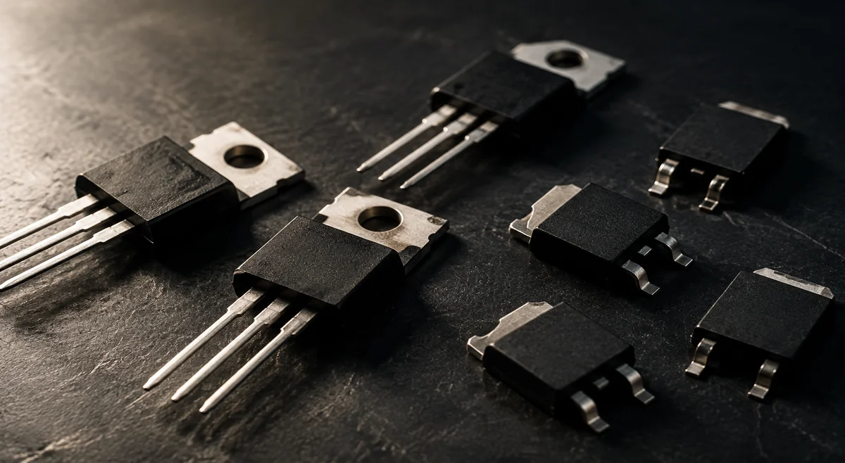
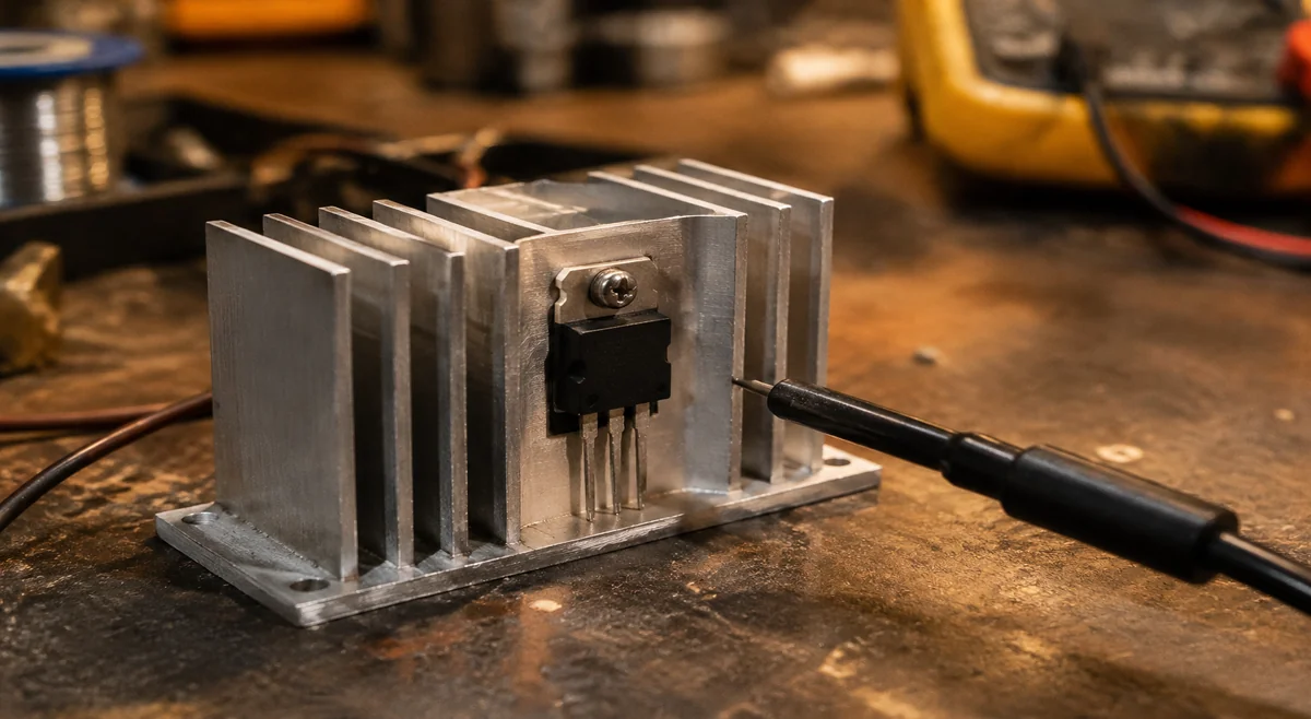
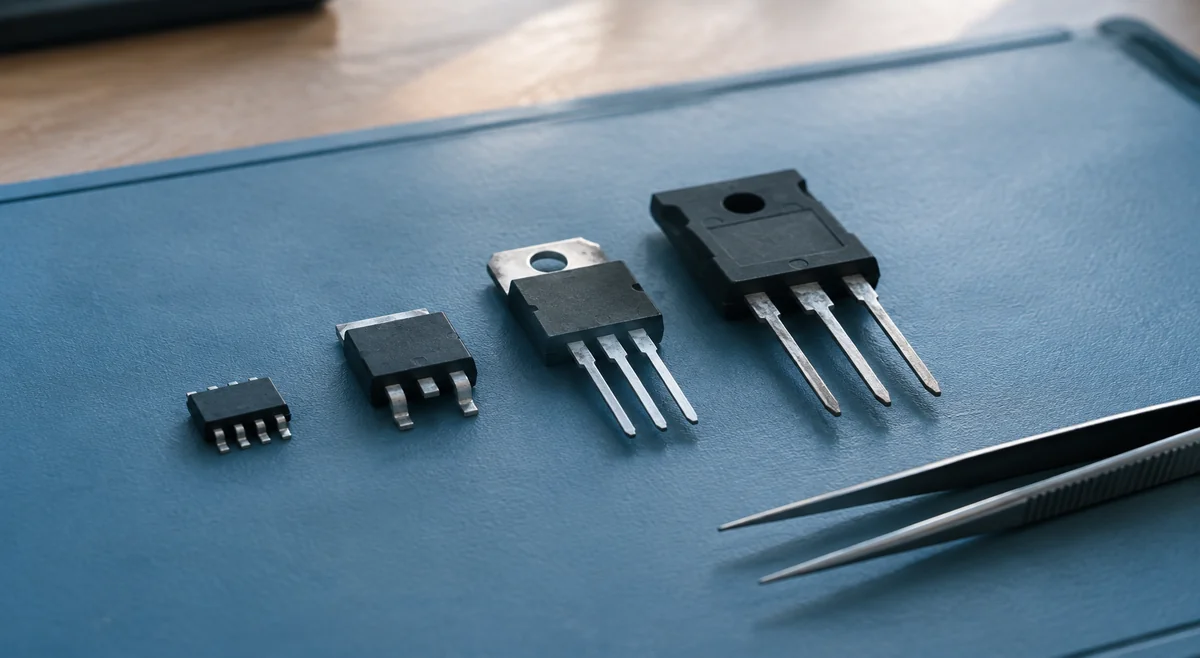
The headline current rating is set by the package and the silicon, and the smaller of the two wins — which is why a TO-220 part and a tiny surface-mount part can share a silicon family yet differ wildly in usable current. In practice, heat is the limiter: compute I²R with the hot on-resistance, multiply by the thermal resistance of the mounting — heatsink or copper pour — and check the resulting junction temperature against the derating policy. For pulsed or linear operation, the safe-operating-area graph overrules every headline number. A part chosen on current rating alone, without this thermal check, is a guess; field failures are how wrong guesses get discovered. Buyers choose between two TO-220 parts on headline current while ignoring that one assumed an ideal heatsink in the fine print. The thermal check is ten minutes of arithmetic against a field return. Package choice is part of the same check: a TO-220 with a real heatsink survives dissipation that would cook a D2PAK relying on copper pour alone — while the D2PAK wins on board space and assembly cost where the dissipation math already worked out.
Selection snapshot: four real parts
Four stocked parts show how the framework collapses into a decision. IRF540NPBF, IRF3205PBF and IRFZ44NPBF are standard-level TO-220 devices for switched loads with proper gate drive — motor drivers, power switches, and similar jobs where 10 V-class drive is available. STP55NF06L is the logic-level member of the group, specified for direct drive from low-voltage logic, which makes it the natural pick when a microcontroller pin is the only driver in the circuit. The trade-off is not which is best but which matches the drive available: standard-level parts punish weak gate drive with heat, while logic-level parts answer the case where no driver stage exists. Confirm the Rds(on) test conditions per each datasheet, then match the family to the driver.
Market reality and buying practice
Classic TO-220 MOSFETs are among the most widely listed discretes on HQBuy and LCSC, and that broad coverage cuts both ways. Second sourcing is easy, but suffix discipline is critical: the PBF lead-free suffix must match the BOM character for character, and a part without it is a different orderable device. Popular TO-220 types are also a known counterfeit hotspot — remarked or refurbished parts circulate in the open market — so state original-manufacturer and channel requirements in the RFQ, and see authorized vs independent supply. A Douyin repair-channel video by @朝锋家电维修 (872 likes, observed 2026-09-30) walks through telling genuine MOSFETs from counterfeits at the repair bench — 开关电源老是炸管,教你一招,如何分辨MOS管是不是正品. As always, search the complete ordering code for real-time listings and reconfirm availability for the required quantity before committing.
- Match the complete ordering code exactly — PBF and other suffixes are part of the identity.
- For popular TO-220 types, require original packing and traceability; price outliers deserve skepticism.
- Reconfirm availability against your quantity and delivery date; listings are leads, not allocations.
Frequently asked questions
Quick answers to the questions buyers ask most about choosing MOSFETs.
- Q: Can a microcontroller pin drive a MOSFET directly? A: Only a logic-level device whose Rds(on) is specified at your gate voltage. A standard-level part will linger half-enhanced, run hot and fail early.
- Q: Is Vgs(th) the voltage that turns the MOSFET fully on? A: No — that is where conduction just begins. The Rds(on) test condition in the datasheet tells you where it is fully on.
- Q: Lower Rds(on) is always better, right? A: For conduction, yes — but big low-Rds(on) dies carry the largest gate charge, which can make them the worse choice in fast PWM behind a weak driver.
- Q: Two parts have the same headline current rating — are they equivalent? A: Compare on-resistance at the same gate voltage and at temperature. Parts that look equal at 25 °C often separate clearly once heat is included.
Manufacturer references
Use the latest guidance for the exact part and manufacturer when deciding acceptance criteria.