Crystal or oscillator: the first fork in the road
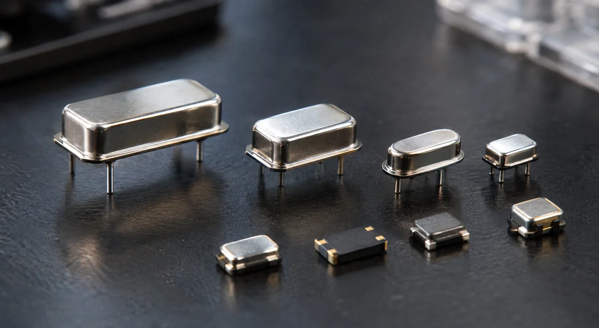
A passive quartz crystal is not a clock by itself. It is a frequency-selective resonator that needs the oscillator circuit inside the MCU or chipset, plus two correctly sized load capacitors, before it produces anything useful. An oscillator — XO, and its compensated relatives TCXO, VCXO and OCXO — is a finished clock: power in, square wave out, no external capacitors and no startup-margin math on your side. ECS's ECS-327MVATX-3-CN-TR illustrates the packaged route: a 32.768 kHz oscillator with ±25 ppm stability from -40 to +85 °C that accepts any supply from 1.6 to 3.6 V, so one part covers several logic levels. The tradeoff is design effort against unit cost and supply flexibility. A passive crystal is cheaper per unit and easy to second-source across makers, but it pushes the engineering onto you: load-capacitor matching, startup margin at temperature extremes, and layout sensitivity around the oscillator pins. A packaged oscillator costs more and narrows the second-source field, but it deletes those variables from your schedule — and a TCXO or OCXO is the only honest answer when the frequency-error budget is tighter than a plain crystal can hold. Decide early, because the choice is hard to reverse. If the product carries RF, precision timing, or a hard frequency-error budget across temperature, price the oscillator option during architecture — not during EVT when the crystal fails the budget. If the board is a cost-driven MCU design with a tolerant clock requirement, a passive crystal matched to the MCU's oscillator is the economical default, and the platform comparison in ESP32 vs STM32 is a reminder that the MCU choice often shapes the clock choice with it.
- Passive crystal: resonator only — needs the MCU oscillator circuit plus matched load capacitors.
- Packaged oscillator (XO/TCXO/OCXO): finished clock output; removes matching and startup work at higher unit cost.
- Tight ppm budget or wide temperature swing: evaluate TCXO/OCXO before committing to a crystal.
- Crystals second-source more easily; finished oscillators buy performance guarantees.
Load capacitance: match the number, don't guess it
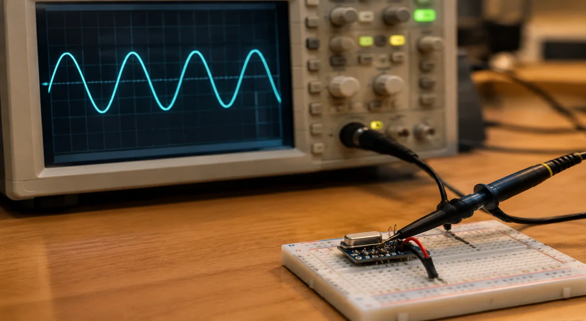
Every crystal datasheet names a load capacitance (CL): the external capacitance the crystal must see to oscillate at its marked frequency. The classic mistake is treating the two external capacitors as equal to CL, or forgetting what the MCU itself contributes. ECS gives the working form — CL ≈ ((Ca + Cin) × (Cb + Cout)) / ((Ca + Cin) + (Cb + Cout)) + Cstray, where Cin and Cout are the MCU pin capacitances — and insists those pin capacitances and the PCB stray capacitance be counted too. In their worked example with an STM32H5 (5 pF on each oscillator pin, roughly 3 pF of stray), the correct external capacitors land at 30 pF for a 20 pF CL crystal; a companion example on the lower-drive STM32L1 needs only 5.1 pF for an 8 pF CL part. The payoff goes beyond frequency accuracy. A lower CL means the oscillator circuit works less hard: in the same ECS analysis, the 8 pF crystal showed an oscillator margin around 12.7 on the low-drive STM32L1, while the 20 pF part managed about 5.3 on the stronger-drive STM32H5 — margin being the ratio of what the MCU can drive to what the crystal demands. Picking CL to suit the oscillator, rather than copying the most common catalog value, is one of the cheapest reliability upgrades in crystal selection. Treat stray capacitance as an estimate, never a constant: a few picofarads on a tight four-layer board, more on long two-layer runs. Always verify the actual oscillation frequency on the finished PCB and adjust the capacitors if the stray estimate was off — a small frequency error now is cheaper than a field return later.
- CL is a matching target: external capacitors plus MCU pin capacitance plus stray must equal it.
- Pull Cin/Cout from the MCU datasheet; never assume they are zero.
- Lower CL generally means easier startup and faster start on weak-drive MCUs.
- Verify frequency on the finished board; stray capacitance is estimated until measured.
Tolerance vs stability: build the ppm budget
Two ppm numbers on every crystal datasheet answer different questions. Frequency tolerance is the initial accuracy at room temperature — how far from the marked frequency the part may sit fresh out of the reel. Frequency stability is the additional drift across the rated temperature range. They add: a ±20 ppm tolerance part with ±50 ppm stability can sit ±70 ppm from nominal at a temperature extreme, before aging is counted. ECS's ordering table makes this concrete: ECS-400-8-33Q-JES-TR is listed as a 40 MHz AEC-Q200 crystal with ±20 ppm tolerance, ±50 ppm stability and 8 pF load capacitance — the JES suffix encodes exactly that combination, which is why the full ordering code belongs on the purchase order, not just the series name. The buyer decision is budget arithmetic. Write down what the application tolerates — UART baud error, USB clock accuracy, RF channel spacing — then sum tolerance, stability and aging, and compare. Do not buy a wider temperature range than the product will ever see: stability specified to +125 °C is insurance that pays nothing on a board that never leaves a mild enclosure.
- Tolerance is room-temperature accuracy; stability is drift across temperature — budget both, plus aging.
- Read the full ordering code: tolerance, stability and temperature range are encoded in the suffixes.
- Size the ppm budget to the application, not to the tightest number on the datasheet.
- Match the temperature rating to the real enclosure, not the worst case you imagine.
ESR and drive level: why small crystals sometimes refuse to start
Equivalent series resistance (ESR) is the crystal's internal loss, and the oscillator circuit must overcome it. The headroom is the startup margin — roughly, how much stronger the MCU's drive is than the minimum the crystal needs. Smaller packages and lower frequencies tend toward higher ESR; Infineon's crystal selection app note states plainly that ESR varies inversely with crystal size. That is the hidden cost of miniaturization: the 2.0 × 1.6 mm part saves board area but asks more of a weak oscillator circuit. ECS's own ordering table shows the spread: an 8 MHz AEC-Q200 crystal listed at 500 Ω ESR next to 33 and 40 MHz parts in the same 3.2 × 2.5 mm package at 40 Ω — the number belongs to the exact frequency and package, never to the series name alone. Drive level is the other side of the same coin. Too little drive and the crystal never starts; too much and you overstress the quartz, accelerating aging or worse. A classic startup-margin trap: a board that starts reliably on the bench at room temperature, then refuses to wake from sleep on a cold morning — the margin was adequate at 25 °C and marginal everywhere else. For ultra-low-power MCUs, filter first on low ESR and low CL, then confirm the margin at the cold-temperature, low-voltage corner — not just on the bench. Reserve the tiniest packages for MCUs whose oscillator circuits are specified to drive them.
- ESR is the loss the oscillator must overcome; check it for the exact frequency and package.
- Smaller packages generally mean higher ESR — miniaturization has a startup cost.
- Keep drive level inside the crystal's rating in both directions: no-start versus overstress.
- Qualify startup at cold temperature and low supply voltage, the worst corner, not the bench.
Package, temperature grade and reading the ordering code
Package choice is a three-way tradeoff between board area, startup headroom and assembly robustness. The standard footprints — 3.2 × 2.5 mm, 2.5 × 2.0 mm, 2.0 × 1.6 mm — shrink the crystal but typically raise ESR and demand more from the oscillator, while larger cans tolerate rougher handling and reflow. Automotive-qualified lines such as ECS's AEC-Q200 ECX-33Q family extend the temperature rating to +125 °C on the widest-range variants for engine-bay and industrial environments. Teams often discover they have been paying an automotive-grade premium for years on a consumer product, simply because the original BOM was copied from an industrial design. Match the temperature grade to the real enclosure: an extended-range rating is insurance you only need if the product can actually get that hot or cold. Finally, treat the ordering code as the contract. In ECS's numbering each suffix position encodes load capacitance, tolerance, stability, temperature range and packaging — order "the series" instead of the full code and you may receive a different CL or stability than the design was validated with. RFQ the complete code every time (how to write an RFQ that gets a useful answer), and when qualifying a second brand, re-validate the full parameter set rather than assuming the series name transfers — the discipline is covered in find alternative components safely.
- Smaller package: less area, higher ESR, tighter startup demands — choose with the MCU's capability.
- AEC-Q200 and extended temperature grades serve harsh environments; do not spec them by habit.
- Every suffix in the ordering code changes what ships: CL, tolerance, stability, temp range, packaging.
- Second-source across brands by re-validating parameters, never by matching the series name.
Frequently asked questions
Quick answers to the crystal selection questions buyers ask most.
- Q: Can I use a crystal with a different load capacitance than the MCU reference design? A: Only if you redo the matching math. Recalculate the external capacitors from the new CL with the MCU pin capacitance and stray included; the wrong CL shifts frequency and can erode the startup margin.
- Q: Is a TCXO worth the premium over a plain crystal? A: When your ppm budget — tolerance plus stability plus aging over the real temperature range — cannot be met by any plain crystal, or when the chip has no oscillator circuit and needs a finished clock. Otherwise the plain crystal usually wins on cost and second-sourcing.
- Q: Why does my crystal start on some boards but not others? A: Startup margin varies with MCU drive-strength spread, capacitor tolerance and temperature. Re-qualify at the cold, low-voltage corner and consider a lower CL or lower ESR part before blaming the layout.
- Q: What exactly should I put on the RFQ for a crystal? A: The complete ordering code including all suffixes, the quantity and packaging, and a request that the supplier confirm tolerance, stability, load capacitance and temperature range against the maker datasheet for that exact code.
Sources
Use the latest guidance for the exact part and manufacturer when deciding acceptance criteria.
- ECS — The Impact of Load Capacitance on Crystal Oscillator Designs
- ECS — ECX-33Q family page with ECS-400-8-33Q-JES-TR variant table (40 MHz, ±20 ppm / ±50 ppm, 8 pF, -40~+125 °C)
- ECS — ECS-327MVATX MultiVolt crystal oscillator product page
- Infineon AN95089 — PSoC 4/PRoC BLE Crystal Oscillator Selection and Tuning Techniques